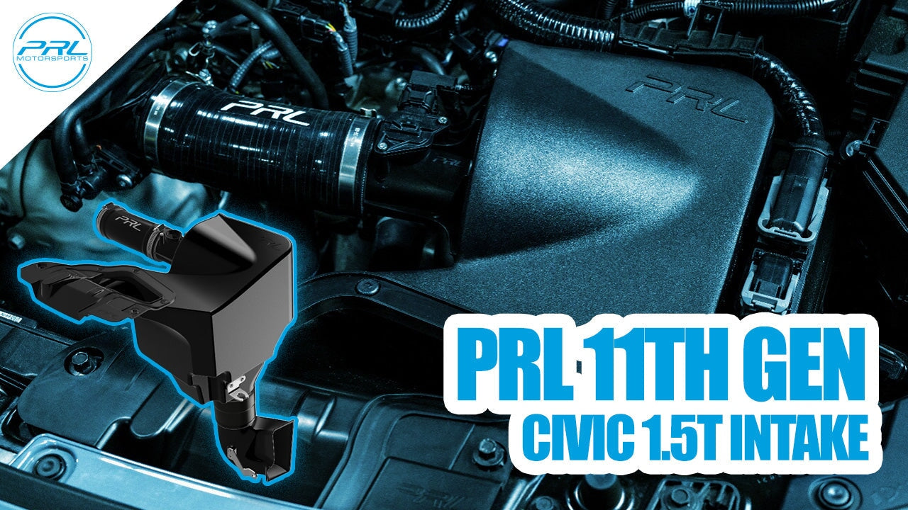
Shown here is the factory airbox on the 11th generation 1.5T cars. The entranceway for air into the airbox is limited to this rubber tube connecting to the factory inlet duct, which mounts to the core support and seals to the hood.
The diameter of the rubber tubing into the airbox is 73.5mm, which makes the cross-sectional area 4243mm². Since removing as many restrictions from the intake system will allow the engine to breathe more freely, our first goal in designing the intake system was eliminating as many restrictions as possible. The shape of the factory duct, shown below, is restricted to that size and shape, due to the shape of the hood and core support. No restrictions could be eliminated there, however, integrating the shape of the duct into the actual airbox itself, instead of connecting to it using a measly rubber tube, would make the new cross-sectional area for air flow equal to the duct opening instead of the tube diameter.


Shown above is the integration of the factory duct shape into the airbox, which entirely eliminates the rubber coupler. We also removed the grating, to open the area up as much as possible. Earlier, we said the inlet into the stock airbox measures 4243mm². With integrating the inlet into the airbox, we were able to step up the minimum airbox inlet cross sectional area to 10,265mm², which is an increase of 83%!
Once we removed the largest restriction in the intake system, our focus then shifted to reducing inlet temperatures. Studying how and where air is fed to the airbox, the inlet duct is fed air by a sort of rubber snorkel in front of the radiator, which can be seen in the picture below. (Duct for the EX model shown).

As we all know, with these cars, heat soak is a huge issue. During rigorous, back to back testing under high load situations, we saw coolant temperatures as high as 240°F! Keeping this in mind, we had to devise a way to lower intake temperatures without blocking airflow to the radiator using some sort of large scoop, drawing air from the grille and impeding airflow.

We knew there was a handy dandy opening right behind the frame rail, where fresh, cool air existed. Drawing air from underneath provides a few large benefits.
First and foremost, utilizing a dual intake design, we were able to further reduce restriction into the airbox by increasing the cross-sectional area, all without blocking any airflow to the radiator. With the addition of the HV+ Duct, the cross-sectional area is increased from 10,265mm² to 14,825mm², which is an additional increase of 36%!

Furthermore, this air is located completely out of and away from the engine bay, which means that it introduces more nice, cool and dense air to the intake system. Since the intake utilizes two air openings, it essentially means that the standard intake area acts as an air bypass if the HV+ duct were to become submerged in water, which prevents hydrolock.


