
Introduction and Process
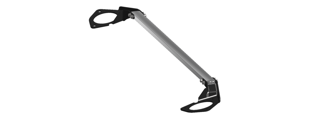
Over the past few months our engineers have been working behind the scenes to bring a cost-effective, functioning and aesthetically pleasing strut tower brace. As a company founded by enthusiasts with grassroots racing history dating back into the late 90's our team understands the importance of keeping Honda's racing heritage alive. The goal of our Throwback Strut Bar project was to design a strut bar that was as light and structurally rigid as possible while reminiscent of the OEM strut bar offered on the DC2 Acura Integra Type R. Our team worked to ensure fitment on both the 2017-2021 Honda Civic Type-R FK8 and 2016-2021 Honda Civic 1.5L Turbo, as well as maintain a competitive price point. In order to develop the most effective design, in terms of weight and structural rigidity, we utilized numerous designs and stress analysis tests to confirm our hand calculations and determine how much stress a strut bar would be experiencing in a real-world scenario.

Analysis
The design of the FK8 front suspension is similar to that of a MacPherson Strut, with the exception of having a dual-axis geometry. Essentially, Honda’s dual-axis design adds a damper fork to reduce the center offset. This minimizes torque steer, but doesn’t affect suspension travel geometry.
In order to simplify the analysis, we had to make a few assumptions. We are considering an FK8 cornering at 1G, therefore, there is 100% weight transfer to the front wheels. Dissecting a free body diagram, we can see, during cornering, there is a frictional force acting along the tire, towards the center of the vehicle. This is the frictional force that opposes the sliding friction, as per Newton’s Third Law. This frictional force creates a friction moment at the control arm, causing it to pivot clockwise or counter clockwise (dependent on cornering direction). Due to that moment, there is a reaction force at the strut bar due to the frictional moment. This force is what we need to calculate.
According to Honda, the curb weight of a fully optioned 2021 FK8 is 3121 lbs with a weight distribution of 62.1 : 37.9. This means that the force produced via friction at the tire, due to the 1G cornering, is equal to 3121 lbs * 62.1%, which is 1938 lbs. Next, we need the distance from the ground to the lower control arm, and the distance from the lower control arm to the top of the strut tower. These distances were determined by taking measurements directly from an FK8, which are 7.4” and 24.3” respectively. The math for determining the force on the strut bar is shown below.

Once the force acting on the strut bar was obtained, we ran loading simulations for our design. This allowed us to determine the best interior geometry of the strut bar extrusion, in terms of minimizing deflection due to the reaction force. The cross sectional area we chose to constrain all the designs to is 0.5685 in2, which is exactly 50 percent of the cross sectional area of the solid aluminum bar. The goal of this project is to develop a strut bar that maintains optimum structural rigidity while remaining as light as possible. We felt that any more than a 50 percent reduction in material may compromise rigidity, likewise, we felt that any less than a 50 percent reduction may adversely affect the weight. The calculations for determining the resultant load on the strut bar are shown below.

Results

Shown above is the cross sectional pattern that performed the best and was decided on for our strut bar. Not only does this design mimic the design of the original strut bar offered on the DC2 ITR, but it also performed very well under stress due to its double I-beam design. Though this design is similar to the DC2 ITR, it is important to note that our design is significantly larger due to vehicle differences. I-beams are a very common cross section for structures due to their high strength-to-weight ratio. You can see I-beam cross sections anywhere from bridges and buildings to high performance connecting rods.
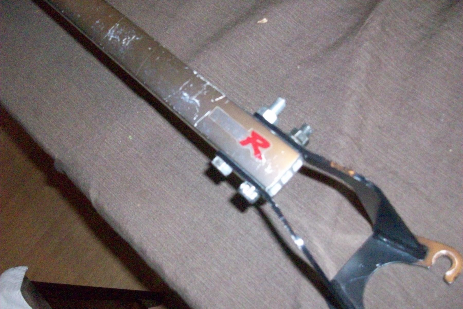
Original DC2 Type R Strut Bar Cross Section
Shown below are the results from the stress analysis on each design. We can see that the loading causes the strut bar to deform downwards, in each case. We started the analysis with a solid cross section to use as a control. The solid cross section actually deformed significantly more than any of the other preliminary designs.


| PRL CTR Strut Bar | |
| Cross Sectional Area (in2) | 0.5685 |
| Force Applied (lbf) | 590.2 |
| Resultant Load (psi) | 1038.2 |
| Deflection (in) | 0.001959 |
| Principal Stress (psi) | 830 |
This table is a compilation of the initial conditions and the data received from the analysis of our design. The deflection result is the maximum deflection experienced by the bar, and the principal stress is the stress normal to the direction of the shear stress. In this case, the principal stress is essentially telling us how much stress is experienced in the direction of the loading.
The key purpose in a strut bar is to keep the struts as aligned as possible and maintain the alignment of the car when the chassis is twisting during cornering, braking or acceleration. A secondary purpose is to tie the two strut bars together, so that they share the load applied, and therefore, reduce fatigue stress in the strut tower sheet metal itself. For both of these conditions, it is most important to focus on the deflection rather than the principal stress. Yes, it is important to consider the amount of stress the material is experiencing, however, the design of the strut bar is not limited by ultimate stress in this situation. The yield stress of 6061 aluminum is 35,000 psi, so there is virtually no real-world scenario in which a strut bar in a car would experience this kind of loading.
According to the results, our design is only deflecting by about 2 thousandths of an inch under loading. Our engineers explored various other designs such as one, two and three piece assemblies, etc and did not find any notable differences in strength and rigidity. We chose not to integrate any additional mounting points such as firewall or brake booster bracing to comply with racing classes. Some racing classes, such as SCCA Street Touring, do not permit the use of 3-point strut bars.
The use of extruded tubing will allow us to keep material and manufacturing costs down (and weight) in comparison to an alternative method such as billet aluminum. Though it's still a bit early in the process to determine final pricing and an ETA, the Throwback Strut Bar should be able to hit the market at an affordable price sometime in Q4 of 2021. FK8 & 10th Gen Civic customers can expect an anodized silver finish on the extrusion and black mounting brackets. Stay tuned for more details and updates!


