
Turbocharger Maintenance Education & Troubleshooting Procedures


Our team has put together an informative guide with preventative maintenance tips to maximize turbocharger reliability and longevity, along with troubleshooting procedures to help diagnose any failure symptoms with possible causes if any issues occur. Often times perfectly functioning turbos are wrongly blamed for oil leaks. It is important to understand how the oiling and sealing system works to help properly diagnose turbocharger or engine related issues. This education will help you save wasted time, money, headache and an unnecessary warranty claim.
Turbocharger CHRA Oil & Sealing System - "My turbo seals are bad!"

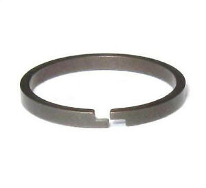
Vehicles and engines use a variety of oil seals, from common O-rings, to lip-type contact seals to split-rings (like a piston ring) - each has its own intended purpose. It is important to note that turbochargers use split-ring(s) to seal both end of the CHRA, due to the high speeds, temperatures and shaft clearances required for proper operation. If oil is found to be leaking from a turbocharger, it can be difficult to properly diagnose, especially without following the proper troubleshooting steps. We should note that there is no way to simply service or change the seal, like replacing an O-ring or rear main seal on an engine. Changing or replacing the turbocharger may not remedy the problem, as the oil leak is often a symptom of another underlying problem with the installation, engine or setup.


Shown Above: Turbocharger CHRA Oil Slinger Grooves
Turbine-Side Sealing:


Turbine-side seals are the simplest of all turbocharger seals. As oil travels through the CHRA and lubricates the bearing assembly, it travels along the shaft until it reaches the hub where it can evacuate. To aid in proper oil evacuation, an oil slinger groove is profiled around the hub to allow oil to be "slung" outwards by centrifugal force and drip down the walls via gravity to be drained back into the engine. At the end of the hub/shaft, one or two split-rings (depending on application) are seated into a precision-machined bore, where the piston rings do not move.
Due to necessary running clearances, split-style rings do not seal 100%. This is beneficial for turbine sealing because of the exhaust gas pressures from the turbine inlet pass behind the turbine wheel, creating a pressurized seal around the piston ring, preventing any oil from escaping the CHRA. The split-ring gap clearance allows for a very small amount of exhaust gas to enter into the CHRA, helping the oil stay inside.


Unlike the turbine-side, compressor-side sealing can be a bit more intricate and dependent on turbocharger manufacturer, design/model, size and/or application. Despite their differences, the goal is the same, though - to allow oil to lubricate the bearings, travel along the shaft and evacuate out the drain without leaking through the compressor or turbine. An oil slinger groove is again profiled, but this time is located at the back of the rotating turbocharger thrust collar. Thrust collars can be a standard disc, or combined with thrust collar and spacer assembly. Like the turbine-side, the compressor-side uses one, two or three split-rings depending on turbocharger.
Pressurized Areas:
There are three areas of pressure inside of a turbocharger:
- Compressor
- Turbine
- CHRA
If the compressor and/or turbine pressure is greater than the pressure inside of the CHRA, oil will not leak out. A properly sealing and functioning turbocharger and engine setup will pressurize the compressor and/or turbine. However, if the pressure inside of the CHRA is greater than the compressor and/or turbine housings, oil may be able to leak past the sealing ring(s).
Compressor and turbine wheels are designed to allow pressure to build up behind the wheels, thus keeping oil from leaking out of the CHRA and helping the sealing rings.
Turbocharger Bearing Systems

Shown Above: Ball Bearing Turbocharger Cutaway

Shown Above: Journal Bearing Turbocharger Cutaway
There are two types of turbocharger bearings systems - journal bearing and ball bearing. Most OE manufacturers use journal bearings for factory turbochargers. Ball bearings are often used in aftermarket, high quality, high performance turbochargers. Each design has its own benefits, but both share one common purpose - to keep the shaft / wheels spinning without making contact with the housings.
Turbocharger Do's & Don'ts
Did you know that only a small fraction of turbochargers actually fail because of manufacturing defects? Most failures are caused by oil starvation/blockage, oil contamination, foreign object damage, abuse/exceeded use, insufficient support mods or improper driving habits.
Oil Starvation / Blockage:
Don't forget the lube! Nobody likes getting into action while it's dry - well neither does your turbocharger's bearings. Always be sure to check your oil levels.
Proper oil levels are only useful when your engine and turbocharger's oil orifices aren't obstructed, though. One of the most common mistakes made when installing turbochargers is the use/overuse of silicone RTV sealant that can clog oil passages, prohibiting oil to properly supply the bearings, and/or engine. Improper oil feed pressures can also starve the bearing system of adequate lubrication.
Though keeping your turbocharger fed with oil is critical, there is such thing as too much oil. Kinked, obstructed drain pipes or improper installation such as CHRA rotation or angle can hinder oil drainage and cause backup in the CHRA. If proper drainage cannot happen, oil will find the easiest point of exit, which is usually through the split-ring seals at one or both sides of the turbocharger (compressor or turbine).
Oil Contamination:
The most common oil contaminates are fine particles. Fine particles are the result of the combustion process, usually containing carbon. These particles are normal, but can act as an abrasive if there is too much contamination. Oil bearing surfaces, shaft surfaces, oil feed orifices and sealing tolerances can be worn because of the abrasive particles. Other particles such as worn engine components, debris or dust/dirt can act the same.
Increased cylinder pressures correlate to increased blow-by and wear. We recommend increasing oil change intervals to reduce oil contamination and monitor oil color. Adequate crankcase ventilation is also critical in alleviating crankcase pressure and contamination.
Foreign Object Damage:
Foreign objects, such as outside debris, engine components or damaged engine internals are a sure way to damage your turbocharger. Always be sure to have an air filter installed while the engine is running. Regularly inspect the filter and perform filter maintenance. If an air filter or compressor inlet tube(s) are not installed, make sure no foreign objects such as nuts, bolts, etc. can enter the intake track to be sucked into the turbocharger.
In the event of a catastrophic engine failure, the debris typically exits the engine somewhere, usually through the exhaust. Piston, valvetrain, cylinder wall debris, etc., can make contact with the turbine and cause damage. It is recommended to inspect the turbocharger for damage anytime an engine failure is experienced. When installing a previously installed turbocharger that from a damaged engine, the risk of contaminated oil passages and charge air tracks are high, increasing the risk of turbocharger damage.
Turbocharger Abuse & Exceeded Use:
Though manufacturers may provide a power rating for certain products (usually power is rated at the crank, not to the wheels), this does not mean max component reliability will be experienced at this rating. Typically product power ratings are listed at peak power - customers should not expect maximum longevity or reliability at maximum power output. There is a reason automobile manufacturers do not release vehicles or components at maximum capabilities.
Just as components typically aren't designed to withstand optimal longevity at peak power, turbochargers and other wear & tear components are also not designed to withstand peak power for extended periods of time. Different driving styles will exert different stresses and loads onto different components. For this reason, most turbocharger and product manufacturers do not warrant race or track-use vehicle components. Other abuse such as brake-boosting, anti-lag and/or exerting high engine load (i.e. boosting WOT pulls at low RPMs in high gears or with heavy vehicle loads), top-speed runs, long duration pulls (1/2 mile or longer runs) can cause excessive exhaust temperatures and stress.
Shaft Speed & Back Pressure:
Over the years engine and turbocharger designs have changed significantly. These days, most factory turbocharged modern vehicles utilize a small displacement engine with small-frame turbochargers to meet emissions standards while also offering optimal response and fuel economy. Though technology and modern tuning has allowed manufacturers to develop some extremely efficient turbocharger systems, this push for small frame turbos and response has its drawbacks with turbocharger longevity.
Most people are familiar with turbocharger boost pressure (typically measured in PSI), but rarely do folks discuss turbocharger shaft speed (measured in RPM). In the past, turbo speed wasn't monitored by most, as it wasn't a common cause of issues with larger frame turbochargers. Now that smaller frame turbos are becoming more popular, turbo failures due to high shaft speeds are becoming more common.
Generally, the pressure ratio increases as shaft speed increases. However, every turbocharger / compressor will have a choke point, which is associated with maximum shaft speed. As the turbocharger reaches or surpasses this choke point, compressor efficiency begins to drop drastically and turbocharger shaft speed will also be nearing or exceeding its acceptable operating limit. The chances of turbocharger overspeed are very high when operating near the choke point.
Typically, the remedy for compressor choke point is to upgrade a larger compressor wheel. Unfortunately, though, it is not that simple. Manufacturers face major spacing constraints when trying to fit large turbine and compressor wheels into factory location turbocharger upgrades. There is also a desired inducer to compressor ratio for optimal balancing and performance that we have to keep in mind. However, there are other tricks that turbocharger manufacturers can do to increase compressor efficiency, such as anti-surge compressor housings or ported compressor shroud covers. These tricks can help increase airflow by up to 30% (depending on turbocharger and application) and reduce compressor surging.
High exhaust back-pressure is another common issue with factory location turbocharger upgrades. Due to spacing constraints, there often isn't enough room in the engine bay or surrounding areas to increase the size of the turbine or compressor housing(s). Generally, as boost pressure is increased, so is exhaust back pressure. Back pressure can be relieved through a larger turbine wheel or housing. Doing so, however, will hinder turbocharger spool/response and require the room to do so. We at PRL prefer to offer the largest turbine wheel possible to fit a given housing frame to offer the greatest exhaust/power flow and response while remaining a direct-fit turbocharger. It is also important to note the vehicles at higher elevations require the wastegate to be shut more than vehicles at lower elevations to make the same boost and/or power level, ultimately increasing backpressure at the same power output.
Poor Driving Habits:
Another common cause to premature turbocharger failure or wear is poor driving styles or habits such as:
- Hot engine shutdown - causes oil coking around the turbine-side sealing ring and carbon buildup inside the turbocharger, which can lead to bearing failure
- Hard acceleration at cold engine temperatures - does not allow enough time for oil circulation and can cause oil starvation or insufficient lubrication
- Excessive engine idling - can cause oil burning from creating a turbine vacuum. Oil can seep through the turbine-side sealing ring because of this, especially with higher oil pressures at low shaft speeds
Insufficient Supporting Mods:
Just as you wouldn't go run a marathon without proper training or gear and expect to be successful, customers should not expect to have the best performance or success when looking to increase power with an upgraded turbocharger without proper supporting mods. Here is a list of supporting mods to keep in mind:
- ECU calibration - though most modern MAF vehicles can run and drive with factory ECU mapping when using a factory replacement turbocharger, a specific calibration is typically required for optimal performance with a turbocharger change or swap
- Intake system - reducing pre turbocharger restrictions play a key role in allowing the turbocharger to work more efficiently with less effort, thus improving longevity
- Exhaust system - the more air a turbocharger or engine takes in means the more air in must put out via the exhaust. It is important to reduce post turbine restrictions to promote adequate exhaust flow and reduce backpressure. Excessive backpressure can lead to increased exhaust temperatures.
- Fuel system - increased air requires increased fuel for proper combustion and safe cylinder temperatures.
- Charge air system - increased boost pressure and shaft speeds typically mean higher charge air temperatures. Keeping charge air temperatures cool and allowing this increased airflow volume to travel efficiently plays a key role in power delivery and safety.
- Engine internals - Often times aftermarket turbochargers rate peak power higher than factory engine internals can handle. If looking to achieve these higher power numbers, it is important to make sure your engine can handle these goals as well to keep foreign debris out of your turbocharger due to a catastrophic engine failure.
Improper Mods:
Such as turbocharger heat blankets or downpipe blankets can cause premature turbocharger failure to the inability to allow excess heat to escape from the turbine area.
Turbocharger Troubleshooting Guide
Engine/Turbocharger Not Reaching Target Boost:
- Check for boost leaks
- Check for CELs
- Check that wastegate actuator flapper door is operating properly (if applicable)
- Check electronic wastegate calibration (if applicable)
- Check datalogs / tune
- Contact tuner
- Check intake track for obstructions (yes, we have seen shop towels shoved inside)
- Check exhaust track for obstructions (yes, we have seen shop towels shoved inside)
- Check engine health
- Check that shaft/wheels are spinning properly and check bearing health
Check Engine Light:
- Determine the specific CEL codes & perform proper troubleshooting procedures
- Contact your tuner
Turbocharger Making Noise:
- Determine the type of noise the turbocharger is making. Often times turbochargers will make different sounds at various engine loads as compared to your previous turbocharger. It is not uncommon for aftermarket turbochargers to sound different than factory turbochargers
- Check datalogs
- Check for boost leaks
- Check intake track for obstructions
- Check exhaust track for obstructions
- Check that shaft/wheels are spinning properly and check bearing health
Oil Leaking & Smoking:
- Types of smoke:
- Black smoke indicates rich fuel conditions. Check data logs and be on alert for CELs, boost leaks, underboost conditions and intake system obstruction
- White smoke indicates burning water or coolant. Check coolant levels, connections and monitor engine head gasket health
- Blue smoke indicates burning oil for a variety of reasons. See below for possible oil burning reasons.
- Check for external leaks:
- Check all connections and doublecheck installation for tightness. Be sure to use all specified or required torque specs for oil feed bolt(s), oil drain bolt(s). External leaks from recent installation can result in residual oil burn-off inside of the engine bay and/or exhaust system. Improper installation can result in leaking oil burning off inside of the engine bay. Use UV dye if necessary.
- Check gasket(s) for proper seating/sealing
- Rare occasions of a severely leaking compressor or turbine side sealing ring can cause oil to leak out of the CHRA near these connection points. This can easily be identified upon further inspection for internal leaks below.
- Examine your spark plugs:
- You can learn a lot about your engine from looking at your spark plugs. From ignition timing to general air/fuel mixtures to oily combustion, to damaged engine components. If your spark plugs have oil residue on them, oil is entering the combustion chamber somehow. This can occur through a damaged engine, inadequate crankcase ventilation or from a damaged turbocharger.
- Compression and leak-down test:
- It may seem unnecessary, but we always recommending checking the health of your engine. A lot of things can go wrong at any given time and components can wear overtime, especially on the quest for more power. For this reason, we suggest performing a compression test to check each cylinder's compression. One common procedure most folks overlook is a leak-down test, though. A leak-down test will indicate the health or quality of sealing with piston rings, intake valves, exhaust valves, the head gasket or cylinder wall/head cracks. It is possible for a damaged engine to show healthy-looking compression results. Leak-down tests are a surefire way to indicate engine damage.
- Check for internal leaks:
- Remove and examine the intake track, compressor inlet or charge air track. It is normal to have some oily film inside of these tracks due to oil vapors and inadequate crankcase ventilation, but excess oil pooling typically indicates oil leaking through the compressor sealing ring. Oil escaping through the compressor will typically result in the burning of oil in the combustion chamber. Next, remove the downpipe and examine the turbine housing. If oil residue persists, oil is most likely escaping through the turbine-side seal or through the combustion chamber.
- If an internal leak does occur, it is important to check the following:
- Check oil drain line for kinks or obstruction of drainage
- Check oil drain location (if applicable)
- Check oil drain line size (if applicable)
- Check oil feed supply & monitor oil pressure
- Check crankcase ventilation system
Nicks or Marking on Turbocharger Wheels:
- Check compressor and/or turbine wheel(s) for markings from foreign debris. It is normal for the compressor wheel to see some minor wear overtime due to ambient dust and debris. Excessive damage indicates improper filter maintenance or other foreign objects making contact with the wheel(s).
- If location is towards the outside of the compressor and/or turbine wheel(s), inspect shaft/bearing assembly for shaft play or bearing health.


